Systems and processes can be better understood using visualizations representing them from start to finish. This is why data flow diagrams are constructed and effectively used to review processes and systems.
Follow up on this guide to further understand their application, when to apply them, and how they can contribute to your processes.
Table of Contents
- What are Data Flow Diagrams
- Why Make a Data Flow Diagram
- Common Notations and Symbols in DFDs
- Yourdon & Coad and Gains & Sarson Notations for DFDs
- Data Flow Diagram Levels
- How to Make a Data Flow Diagram and Data Flow Diagram Examples
- Final Words
What are Data Flow Diagrams
If you’re wondering what is a data flow diagram (DFD), it is a visual representation representing the flow of data across a system or process. It represents information in the form of inputs and outputs. In simple words, it shows you where data comes from, where it goes, and how it’s being stored.
DFDs can be helpful in better understanding information through a visual map. Such visualizations are used not only to identify how the process or a system works but also to improve efficiency, troubleshoot problems, and identify bottlenecks for mitigation. DFDs can be divided into two types, including logical diagrams and physical diagrams.
Physical DFD: Such a diagram specifies the people, files, software, and hardware involved in the information flow. Hence, physical diagrams are meant to show the process in action.
Logical DFD: This type of DFD is based on how business activities occur without getting into technical details. This type of DFD visualizes the theoretical process.
DFD processes can be broken down to a pseudo code. Such a code is created that is easy to read by people, with the structure of a programming language meant for human reading.
Why Make a Data Flow Diagram
Easy to Understand
DFDs can help explain complex information easily with the help of visual aids. It can also help make the information easy to grasp to retain the audience’s or end-user’s attention when trying to understand the concept.
Clarity of System or Process
A data flow diagram can help clarify how a system or process works. Such a diagram can give team members a clear understanding of the data flow represented visually, making it a blueprint to make business processes more robust.
Troubleshooting Issues
DFDs can help troubleshoot issues by looking at the diagram to identify where an issue might have occurred.
Improved Productivity
DFDs can help improve productivity by reducing the likelihood of error. A clear understanding of a process, complemented by repetition of the workflow, can help enhance productivity. Over a while, the process can be further improved by identifying room for improvement and removing potential bottlenecks.
Common Notations and Symbols in DFDs
Data flow diagrams became popular back in the 1970s for software development. The following notations and symbols are commonly used in data flow diagrams.
- Process: A process notation shows how incoming data is transformed into outgoing data flow. These are depicted as circles or rounded squares.
- Data Store: A data store notation represents the repositories of data in the system. They are sometimes also called ‘files’. The data store symbol is represented as an open rectangle.
- Data Flow: A data flow notation represents the pipeline through which data flows. These are depicted as arrows.
- External Entity: The external entity notation represents objects outside the system. These are the entities with which the system communicates. They represent the sources and the destinations of the inputs and outputs of the system. These are often represented as rectangles or rounded rectangles.
Yourdon & Coad and Gains & Sarson Notations for DFDs
Data flow diagrams have two types of commonly used notations, named after individuals who represented a structure for DFDs. These structures include Yourdon & Coad and Gains & Sarson.
| Yourdon & Coad | Gains & Sarson |
| The Yourdon & Coad notations are used for system analysis and design. The Yourdon & Coad notations are used for system analysis and design. | The Gains & Sarson diagrams are commonly used to visually represent information systems. |
| Processes are depicted as circles. | Processes are depicted as squares with rounded corners. |
| Uses parallel lines for the Data Store symbol. | Uses an open-ended rectangle symbol for Data Stores. |
DFDs are created using graphic design applications and presentation apps, such as with the help of PowerPoint templates. Such data flow diagram templates are often helpful for end users looking to understand how to make a presentation representing data flow. However, since DFD symbols can vary, sticking to a specific notation type is important to ensure consistency.
Data Flow Diagram Levels
Data flow diagrams have levels or layers that help categorize and organize the data. Data flow diagrams can be basic to quite complex. The different DFD levels, starting from level 0, represent the complexity of the diagram. As you construct a diagram, each layer provides more detailed information about the data flow. These layers can then be nested or hyperlinked for a detailed data flow context.
Level 0
Also known as a context diagram, level 0 represents the overview of the information in a simple layout to show the overall process in an easy-to-understand format. It serves as a top-level view of an information system. This DFD level is meant to be simple and lacks complexity for the convenience of the audience or end user.
Components of a Level 0 DFD
- Single Process Node: This represents the entire system as a single process. It’s typically drawn as a circle or rectangle in the center.
- External Entities: These are parties outside the system that interact with it, such as users, other systems, or organizations. They are drawn as rectangles or ovals around the process node.
- Data Flows: Arrows depict the flow of data between the external entities and the process node. They show how input data enters the system and how the system outputs data to external entities.
Example of a Level 0 DFD
We will use a library system to illustrate the different levels of a data flow diagram. In Level 0, the context diagram might show the library management system as the central node, with entities like members, staff, and suppliers. Data flows would include book details, member information, and order details.
Level 1
While level 1 diagrams aren’t as complex as other DFD versions, this level breaks down the single process node from the context diagram into multiple subprocesses, offering a more detailed view of the main system’s functioning.
Components of a Level 1 DFD
- Subprocesses: These are more specific functions or activities within the system, each represented as a process node.
- Data Stores: Introduced at this level, data stores represent where data is held within the system, like databases or repositories.
- Data Flows: More detailed data flows between subprocesses, external entities, and data stores.
Example of a Level 1 DFD
In the library system, subprocesses might include book lending, member registration, and inventory management. Data stores could be member records, book databases, and transaction logs.
Level 2
A level 2 DFD provides a deeper dive into the process or system, further breaking down level 1 processes into more detailed sub-processes. This is an expansion of the Level 1 diagram with additional information. Components of a Level 2 Data Flow Diagram are similar to Level 1, but with each subprocess broken down into finer processes.
Example of a Level 2 DFD
The book lending process in the library system could be broken down into checking member validity, searching book availability, updating loan records, and generating due dates.
Level 3
A DFD level 3 or higher is uncommon due to the detail required to construct such a diagram. Level 3 diagrams are extremely complex, with elaborate details of the system or process in the visual representation. Again, the components of this data flow diagram are similar to the previous level, but with a finer detail appreciation.
Example of a Level 3 DFD
A process like updating loan records in the library system could include verifying loan limits, updating loan status, and handling overdue cases.
How to Make a Data Flow Diagram (with Data Flow Diagram Example)
Data flow diagrams have different elements, each representing vital information. The symbols used in a DFD play an important role in helping to identify different steps of the data flow.
Before you begin making a DFD, it is important to have a basic understanding of the symbols that are used in making a data flow diagram. The symbols used in DFDs include standard notations. These symbols include arrows, circles, rectangles, and text to label the diagram. If you are considering DFD designs for a presentation, they can be similar to concept map templates, mind map templates, and sometimes certain PowerPoint chart templates. However, unlike the aforementioned, flow diagrams use specific symbols to show the system or process.
Note: You might also be interested in our complete guide on how to make a flowchart.
The below examples show how to construct data flow diagrams in PowerPoint using the Yourdon & Coad and Gains & Sarson notations. We used PowerPoint shapes to construct the data flow diagrams in the examples below.
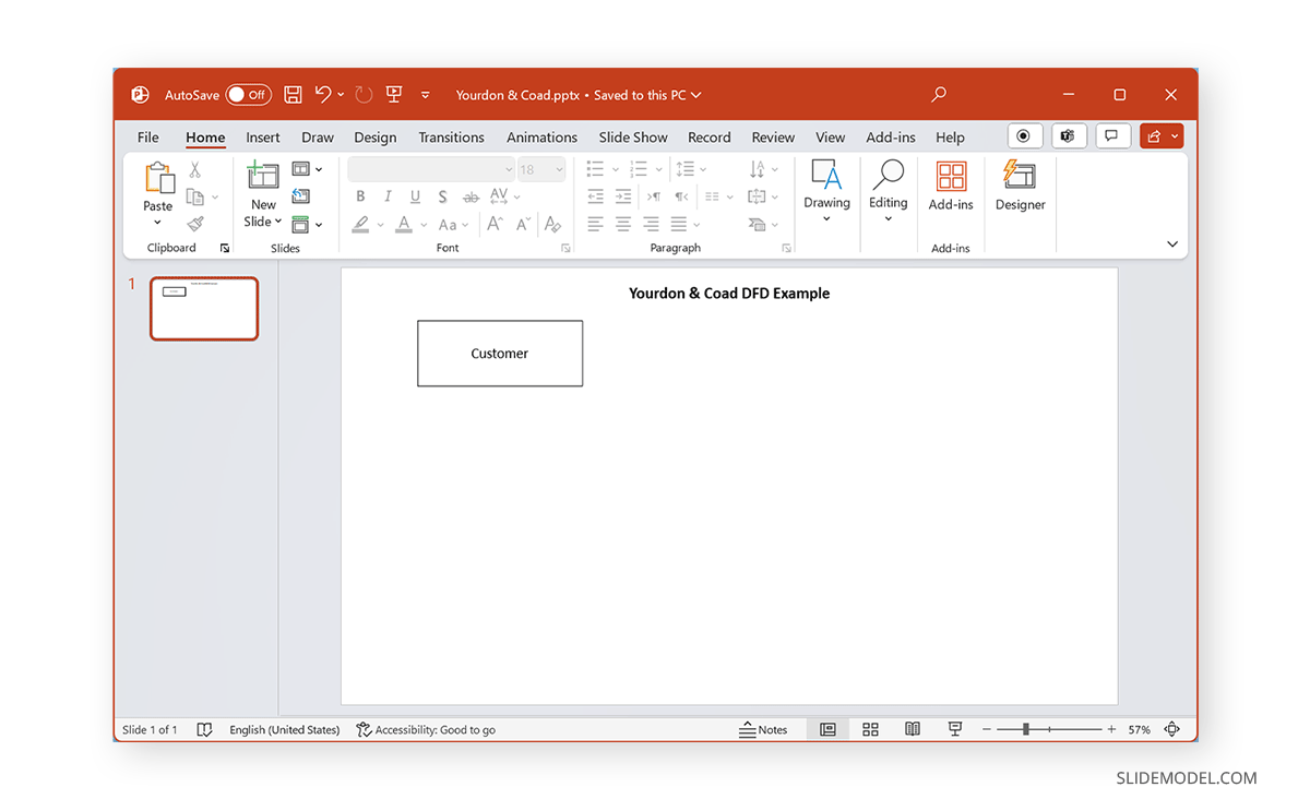
Identify the External Entity
External entities represent the source or destination of information and are placed outside the system represented in the diagram. Such an entity is represented using a stick figure or squares. External entities are terminators, sources, actors, or sinks. When constructing a data flow diagram, you should identify the external entity to represent the source or destination of information.
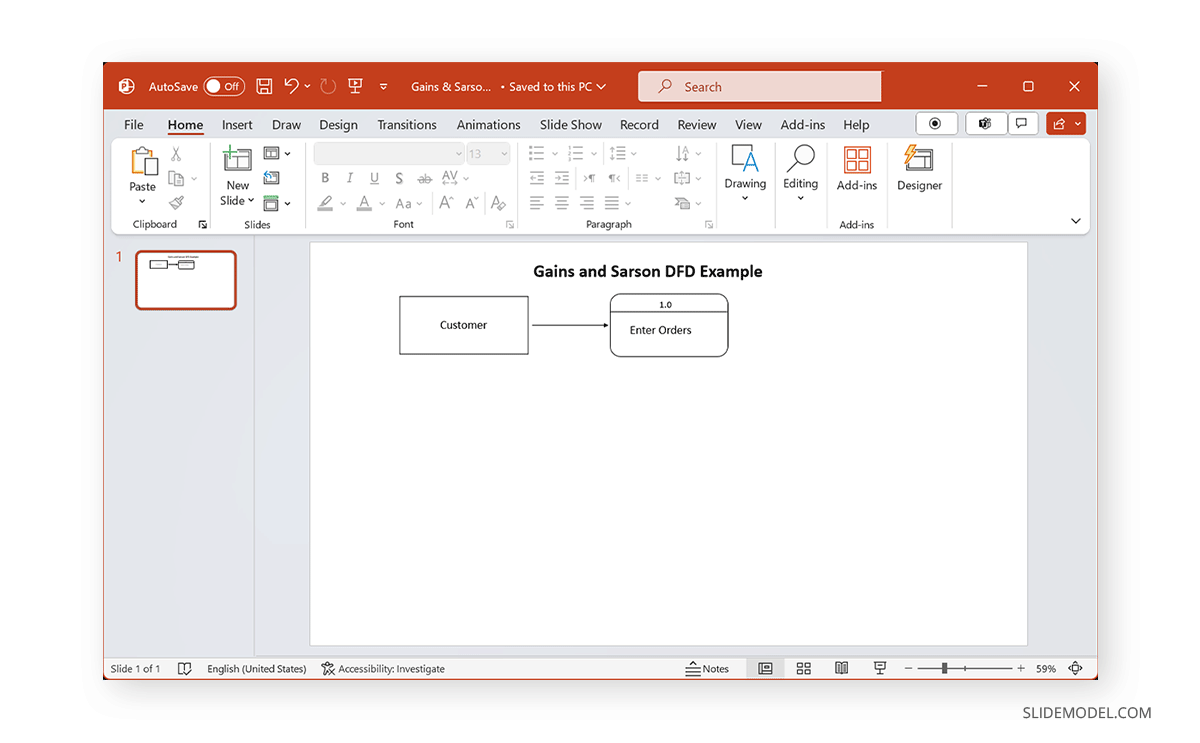
In the example below, we added a customer for an airline service as an external entity when demonstrating a Yourdon & Coad DFD Example.
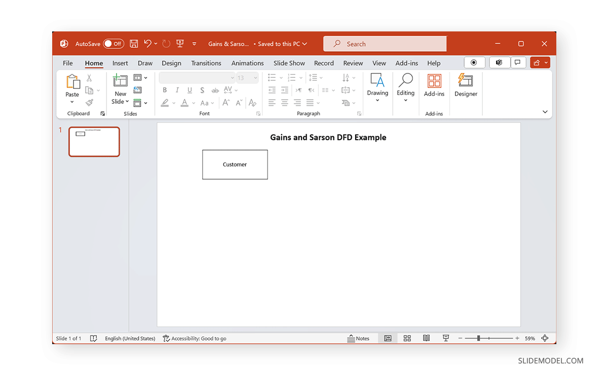
Similarly, for a Gains & Sarson DFD example, our example includes a customer interacting with a process as an external entity using an online shopping cart.
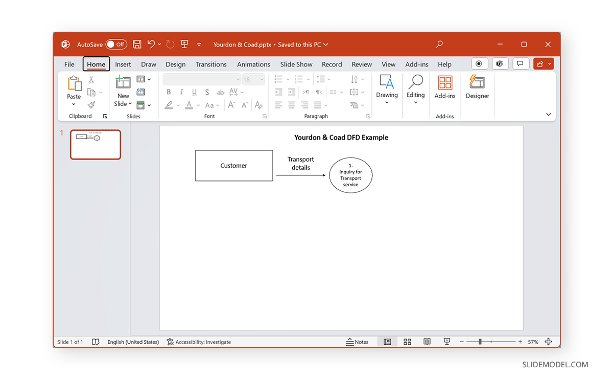
Know the Process
Before a DFD can be constructed, the steps for the system or process need to be precisely identified. Each process should have one or more inputs or outputs. A process symbol shows the procedure in a DFD. Processes often start from the top left of the diagram, representing completion at the bottom left. Process symbols represent the data flow, from incoming data to its manipulation and output. A circle or rounded rectangle is the most common symbol for showing a process.
The Yourdon & Coad example below shows an inquiry for transport service as an example of a process. The arrow, in this case, demonstrates the data flow.
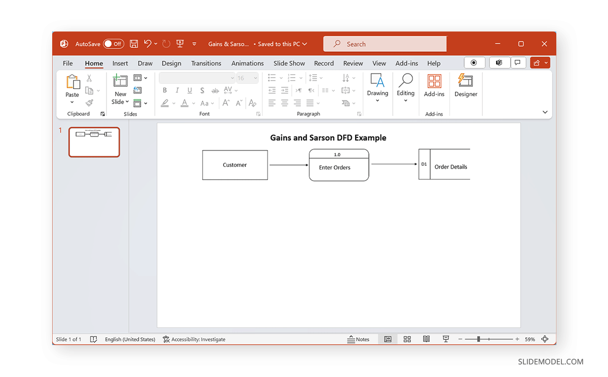
The Gains & Sarson DFD Example shows the process with a rounded rectangle, representing a customer entering a purchase order, with the order’s entry being the process.
Represent the Data Store
The data store symbol represents where the data is kept for later use. This might include files containing documents. The data flow includes moving through a process, a data store, and moving out of the data store (data outputs). Data store symbols, including parallel lines or open-ended rectangles. Each DFD process must be linked to another process or data store.
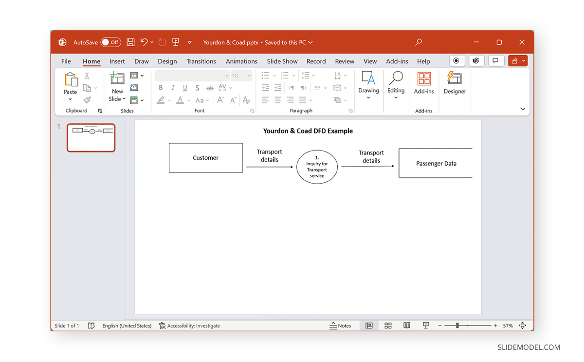
In both our examples, as the data flows, it is stored at a location. The Yourdon & Coad example represents the transport details of the passenger being stored (as shown below).
The Gains and Sarson example shows the storage of the customer order data.
Add Data Inflow and Outflow
The symbol for data flow shows the path from external entities, moving across processes and data stores. Arrows are the most commonly used symbols for data flow in a DFD. The data flow represented on a DFD should have at least one data flow in and one out.
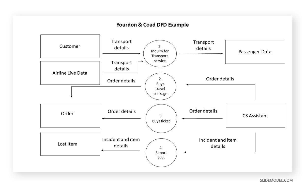
Yourdon & Coad Level 0 DFD Example
The below image shows a Level 0 DFD for an airline ticketing and customer management system.
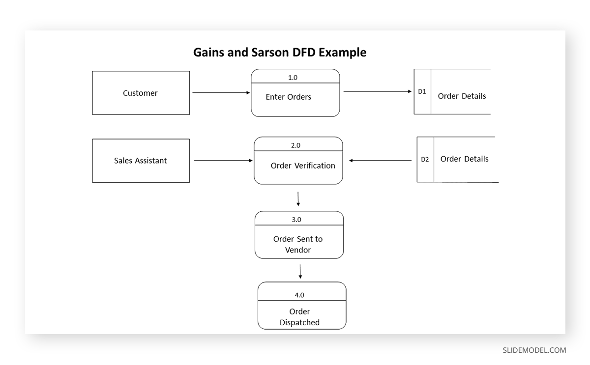
Gains & Sarson Level 0 DFD Example
The Gains & Sarson DFD example below depicts a Level 0 DFD example for a shopping cart where a customer places an order that a sales representative verifies and later processes and dispatched by a vendor with the tracking details of the package.
Final Words
Data flow diagrams can be simple to complex. However, the basic idea behind DFDs is to reduce complexity through visual representation. You can also represent DFDs using a PowerPoint presentation. As a presenter, you can take cues from our articles about how to start a presentation and how to end a presentation to construct a DFD diagram.